Summary
Example of controlling the PowerSwitch Tail II, using an Arduino.
Description
This is an example of controlling the PowerSwitch Tail II, using an Arduino. The PowerSwitch Tail II is a relay that is enclosed in a case.
Why?
Because we can easily control physical devices.
Before We Begin
PowerSwitch Tail II
This example uses using the PowerSwitch Tail II, you can find the product here:
http://www.sparkfun.com/products/10747
Arduino
This example uses the Arduino Duemilanove version of the Arduino board. This board has been replaced by the Arduino Uno. All Arduino stuff can be found:
http://arduino.cc/en/
Upload Code to Arduino
If you don't have the Arduino environment, download it from the Arduino site (http://arduino.cc/en/Main/Software). From here, copy the code from the bottom section labeled "The Code". Paste this into your sketch and upload it to your Arduino. Finally, from the menu, select "Tools > Serial Monitor". With the code uploaded already, enter 1 or 0 to turn the device on or off.
Hooking it up
Simply enough here's how this works.
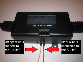
- In my example, pin 13 of the Arduino is connected (by the orange line) to the PowerSwitch "1: +in"
- In my example, Gnd of the Arduino is connected (by the black line) to the PowerSwitch "2: -in"
 |
| Figure 1 - Arduino and Powerswitch Tail II |
 |
| Figure 2 - Arduino |
 |
| Figure 3 - Powerswitch Tail II |
The Code
char incoming_char=0;
void setup() {
// initialize the digital pin as an output.
// Pin 13 has an LED connected on most Arduino boards:
//pinMode(7, OUTPUT);
Serial.begin(9600);
pinMode(13, OUTPUT);
Serial.println("Setup has ended, entering loop()");
}
void loop() {
if (Serial.available())
{
incoming_char=Serial.read(); // Get the incoming char
if(incoming_char == '1')
{
digitalWrite(13, HIGH); // Turn the Powertail on
Serial.println("Switch ON");
}
if(incoming_char == '0')
{
digitalWrite(13, LOW); // turn the Powertail off
Serial.println("Switch OFF");
}
}
}
Do you take into account optimizing your articles for search engines?
ReplyDeleteHi,
ReplyDeleteThanks for the example, it's simple and got it working fast. Is there a reason for the ground to not be connected?
How many of these can be hooked up and used to one Uno at a time?
Thanks
I think the ground on the powerswitch tail ii was to connect to mains ground.
DeleteYou can connect as many as you have pins for. all of the powerswitch tail ii's would share the same gnd pin on the arduino
I haven't tried it but you could control many powerswitch tail ii's from one pin (turning all on or off).
Yes that works.
DeleteSean is correct. According to the PowerSwitch instructions the ground is connected to mains.
DeleteOne thing I've noticed on my PowerSwitch Tail is that when current is first applied to it (for example, when code is uploaded to Arduino and PS plugged in) the relay opens and closes very quickly for a second.
Has anybody experienced this?
The code works fine.
I believe the explanation is the bootloader is using pin 13 on startup. I'll try to find a link to support it. On startup, the pin will go HIGH/LOW quickly but briefly, many times.
DeletePin 13 is used in the examples because for most arduinos, there is a built-in LED connected to digital pin 13. This means that its easier to see that something is working. In practical applications, I would avoid using pin 13 for relays because of the reason you mention.
I try to control the on off of a LED light bulb with it, in the on position the bulb light up very bright but in the off position the bulb still has an extremely dim light (not totally off). Did you try any LED light bulb?
ReplyDeleteI am getting error that says: avrdude: stk500_getsync(): not in sync: resp=0x00 how do I fix this ?
ReplyDeleteI got it to turn on but how do I turn off the light ?
ReplyDeleteNice bllog you have
ReplyDelete